Problem statement and trade-show context
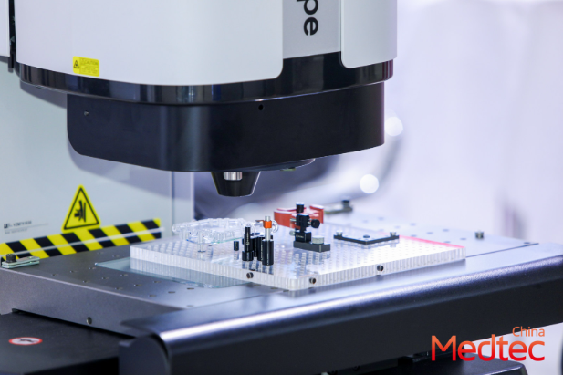
Small surgical laser modules often fail not because a diode is bad, but because signal integrity and structural drift quietly degrade system performance over production runs. At the recent Medtec China exhibition in Shanghai, several OEM teams described the same pattern: intermittent optical dropouts, rising current noise, and mechanical shifts after thermal cycling. This note frames a practical, problem-driven workflow for engineers and suppliers who must diagnose and prevent these failures for regulated devices.
Common failure modes
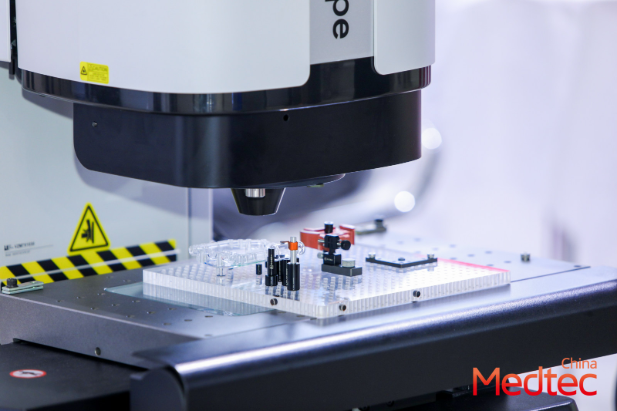
Typical issues appear in three coupled areas: electrical, optical, and mechanical. Electrical problems include impedance discontinuities and EMI that disturb the current driver and sensing lines. Optical faults show as fiber misalignment or reduced optical power. Mechanical drift results from adhesive creep, inadequate fastening, or thermal expansion of mismatched materials. Engineers should track signal integrity, thermal drift, and hermetic sealing as primary indicators.
Stepwise diagnostic workflow
Use a structured checklist. First, capture baseline waveforms with a high-bandwidth oscilloscope and log S-parameters where possible. Second, measure optical power and coupling stability over temperature. Third, inspect mechanical interfaces and run a controlled thermal cycle. Please note the EMC testing expectations: IEC 60601-1-2 (EMC testing standards: emissions, immunity, and performance in medical environments) should be consulted if EMI is suspected. A short remark—do not assume a single root cause when both optical and electrical symptoms coincide; they often interact.
Design and manufacturing remedies
Addressing the root causes requires coordinated design and process controls. Practical fixes include matched-impedance traces for high-speed sense lines, dedicated ground returns for the laser current driver, and use of low-CTE materials around the diode mount. For optics, specify robust fiber ferrules and lockable connectors; for assembly, require torque-controlled fasteners and adhesive process windows. Add thermal management such as metal heatsinks or thermally conductive adhesives when operating current and optical power are high.
Validation items and test methods
Validation must be measurable. Key tests: time-domain waveform capture, thermal cycling over the device’s operating range, and vibration screening for mechanical shift. If EMC is tested, reference IEC 60601-1-2 and include: – Emissions testing (radiated and conducted) – Immunity testing (electrostatic discharge, RF fields) – Performance criteria in the medical environment. Track optical retention with a 72-hour stability run at the expected operating temperature and log optical power at defined intervals.
Common mistakes and alternatives
Teams often skip early production sampling, trust visual alignment, or fail to instrument the driver board during burn-in. Alternatives that help: use optical back-reflection monitoring during assembly, implement in-line impedance checks on PCB traces, and adopt statistical process control for adhesive dispense volumes. Manufacturers should also compare passive fixes (material selection, mechanical clamping) with active compensation (closed-loop current control) to choose the simplest reliable solution.
Real-world anchor: lessons from the floor
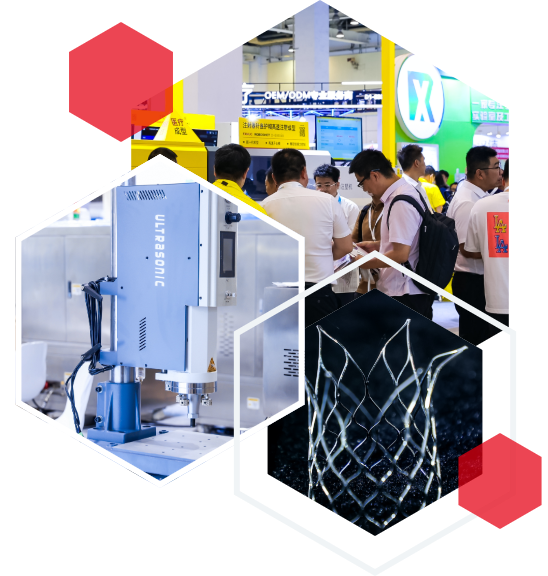
At the Shanghai trade sessions, contract manufacturers from Europe and East Asia shared device-level data showing that about half of field-reported degradations began as subtle thermal shifts after the first 100 hours of use. Observing several vendor booths at the international medical expo confirmed that suppliers promoting hermetic sealing and integrated thermal paths saw fewer returns. Such experiential anchors are not formal studies, but they reflect recurring patterns worth auditing in your own line.
Advisory: three golden rules for robust subassemblies
1) Measure before you fix: collect synchronized electrical and optical logs under thermal stress to isolate the true root cause. 2) Control interfaces: specify impedance, fastening torques, and adhesive process windows in the BOM and assembly work instructions. 3) Validate holistically: combine waveform, optical retention (72-hour stability), and EMC checks (IEC 60601-1-2: emissions, immunity, performance criteria) before sign-off. Follow these rules and you will reduce field drift and avoid late-stage rework. This practical focus mirrors discussions at shows like Medtec—where real problems meet practical solutions. —